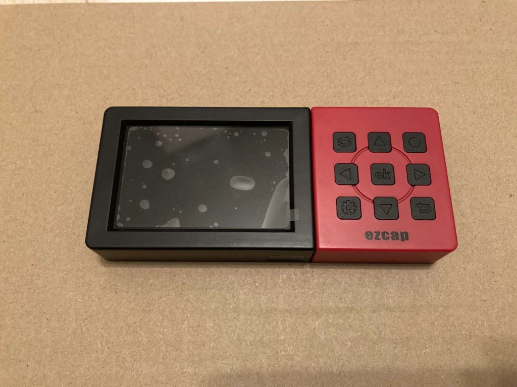
Today the device to be tear-downed is an EZCap 273A portable recording box. It supports 1080p60hz real-time encoding from HDMI in, and store into TF card. It also has a HDMI output port, for externally monitoring what’s recorded. The micro-USB port on the device is only for charging and recorded data transmitting; it cannot be used as online-recorder. The below picture is an overview of front panel.
The front panel has 9 keys and a 3.5 inch display. The display can show status of the recorder and live view of what’s input on HDMI input port. The keys can control and setting when used standalone, without remote control. The recorder comes alone an IR remote controller, which is not shown in pictures below.
Back side of the recorder. A label on the back side showing model, sn and product name. A reset button hole near edge of the back side, and venting holes and speaker holes on left side and right side of back panel.
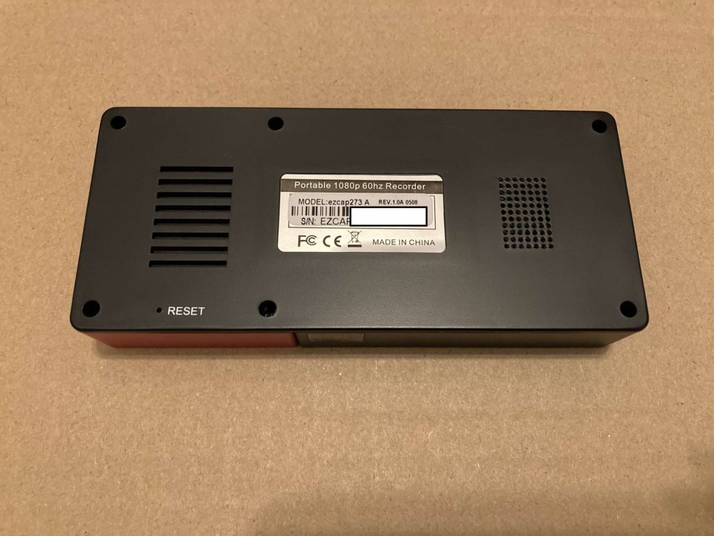
There are 6 screws on back side. 4 on corners, and 2 on middle of two long side. Battery and speaker on back panel side, and PCB on top panel side. Below the PCB is keypad board and LCD board.
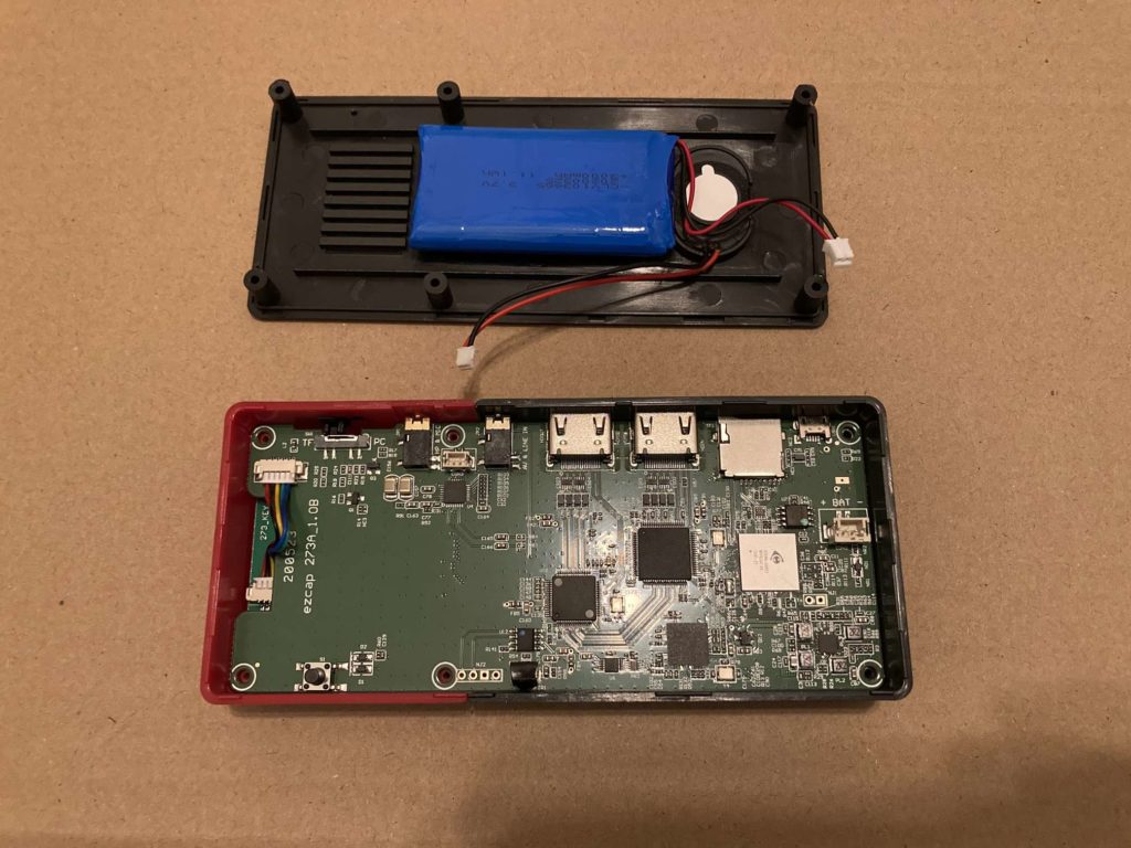
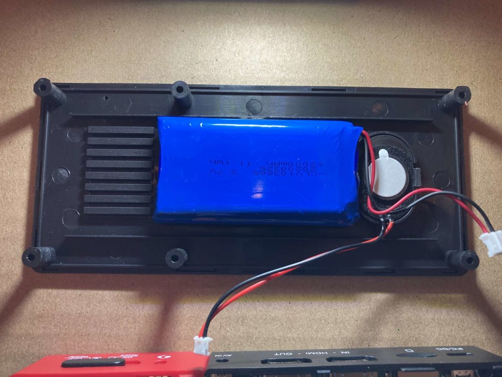
Battery and speaker are glued to back panel with double side sponge tape. Battery capacity is 3000mAh, but drops a lot, may because of long time since out of factory. Now it has to have charging port connected when using. Sound quality is just usable. You cannot expect much from such a small speaker.
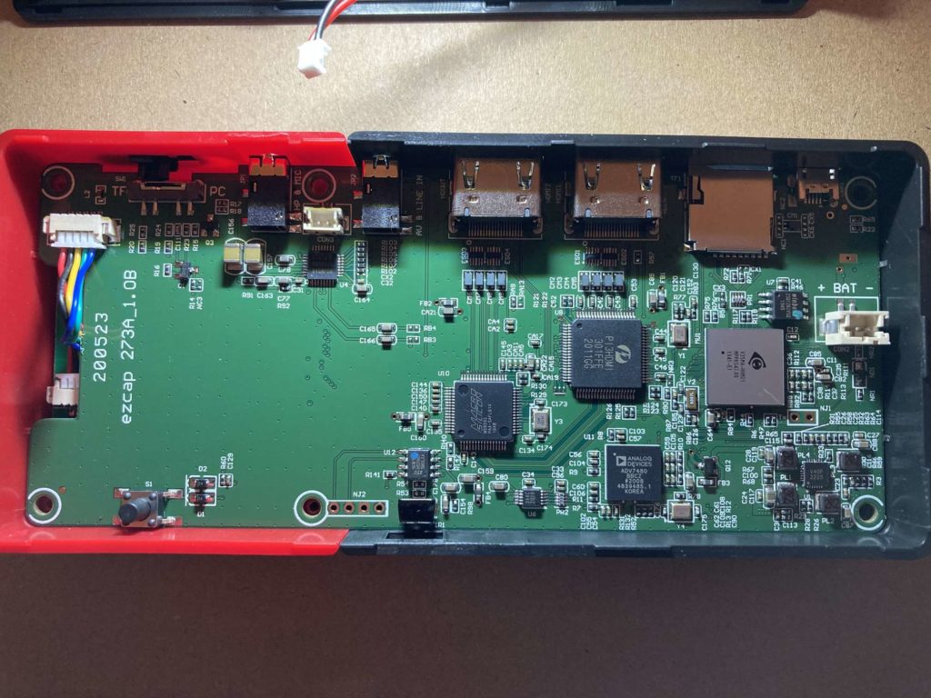
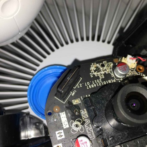
Overview of the main PCB. Chips and components are mainly on left side, that is, HDMI port side of the PCB. Right side of the PCB is nearly empty, except for several components for audio input/output, and reset button, and keypad connection header.
Besides HDMI input, output connector, there also are micro USB connector, TF socket, audio/composite video input and headphone/mic output socket, and power switch. Audio/composite video cable comes with the recorder.
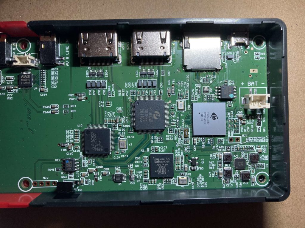
There are 5 main chips, 4 on this side and 1 on back side. From HDMI input, signal goes to MS9332 chip, which is a 1-2 HDMI splitter, dividing input HDMI signal to 2 ways signal. One of the signals goes to PI3HDMI-301FFE chip, a 3-1 mutex, the other goes to HDMI output port. Another input of PI3HDMI is from MS1858, a S-Video to HDMI controller, on the back side. The output signal of PI3HDMI goes to ADV7480, a HDMI receiver, converting HDMI signal to MIPI CSI-2 signal, and then goes to V35MA-HHM21, which is a sports camera SoC. Program inside the SoC encodes input video to H264 format file, then store in TF card.
The separate audio codec WM8960 is responsible for headphone/mic, which is controlled separately, and is out of the signal path of HDMI/composite video.
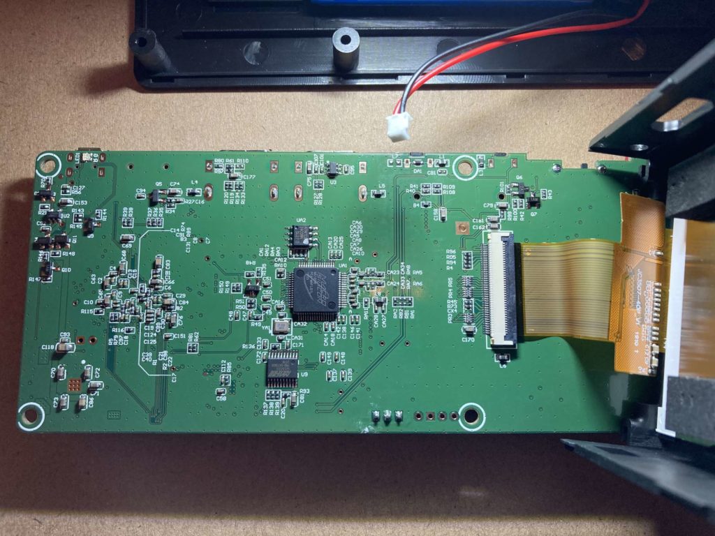
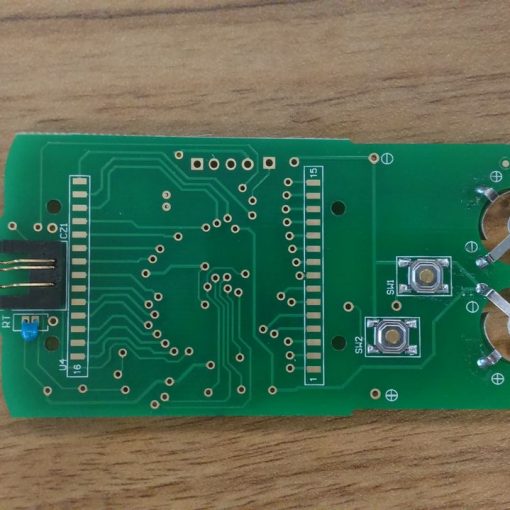
The back side of PCB. The MS8005 is an 8-bit microcontroller, perhaps for configuring HDMI mutex. The MS1858 is described above. Another component is a 40-pin display connector.
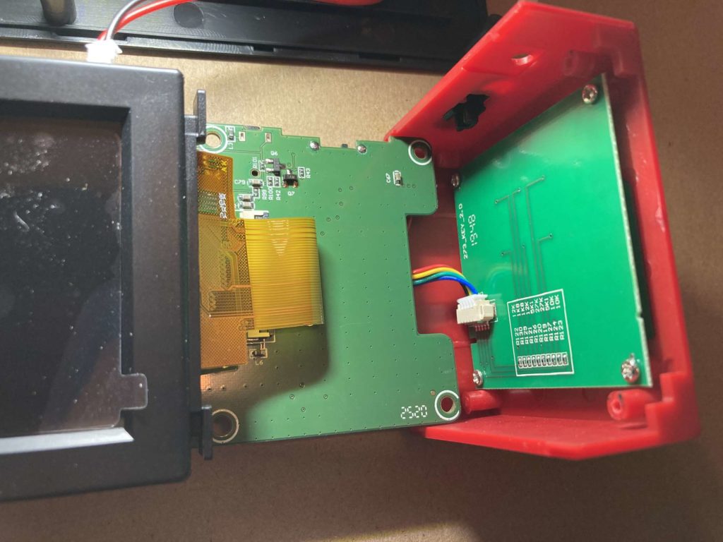
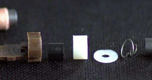
The structure component of LCD part and keypad part are joined using notch. From the silk it can be seen the keypad most likely using ADC key.
The above are major parts of the portable recorder. It is convenient for recording net classes and meetings, with low requirement for computer. (a 1080p60hz capture card can cost an 8th processor computer, or even more. At least 6th gen laptop I own can only capture about 10 fps 1080p video, using a USB capture card.)
[Fin]